Categories
Latest Blog
What do you need to pay attention to when choosing an OTDR?
What specifications do you need to pay attention to when choosing an OTDR?
Did you find that in the actual cable line test, the attenuation and distance results of each manufacturer, unit and model of OTDR may be different? This is determined by OTDR's own performance indicators. Then, understanding these indicators is helpful for OTDR's actual optical fiber measurement. OTDR performance parameters mainly include dynamic range, blind area, resolution, accuracy, etc. So let's have a more systematic understanding.
I. Dynamic ranges
Dynamic range is one of the main performance specs of OTDR, which determines the maximum measurable length of optical fiber. The larger the dynamic range is, the better the curve is and the longer the measurable distance is. At present, there is no unified standard calculation method for dynamic range.
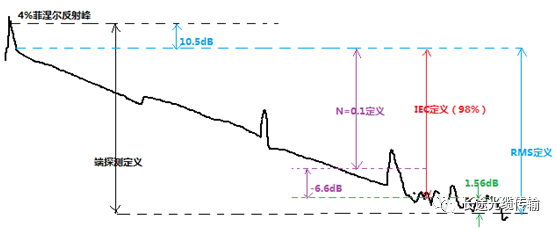
There are four commonly used definitions of dynamic range:
① IEC definition (Bellcore): one of the commonly used dynamic range definitions. Take the DB difference between the backscatter level at the beginning and the noise peak level. The measurement conditions are the OTDR maximum pulse width and 180 seconds measurement time.
② RMS definition: the most commonly used dynamic range definition. Take the DB difference between the backscatter level at the beginning and the RMS noise level. If the noise level is Gauss distribution, the defined value of RMS is about 1.56db higher than that of IEC.
③ N = 0.1dB definition: the most practical definition method. Take the maximum allowable attenuation value when the measured loss is 0.1dB event. The defined value of n = 0.1dB is about 6.6db smaller than the defined value of RMS of SNR = 1, which means that if OTDR has a dynamic range of 30dB, the dynamic range defined by n = 0.1dB is only 23.4db, that is to say, events with a loss of 0.1dB can only be measured within the attenuation range of 23.4db.
④ End detection: the DB difference between the 4% Fresnel reflection peak at the beginning of the optical fiber and the RMS noise level, which is about 12dB higher than the value defined by IEC.
Different definition methods will lead to different results. In any case, the dynamic range is the first indicator of your OTDR price performance. You can check the list given to you by the manufacturer and use two-point calibration to measure the power difference. Of course, a "fool" method, take an optical power device to receive the maximum pulse width of your instrument.
II. Deadzone
Deadzone (Blindzone) refers to the part of OTDR curve that can not reflect the state of optical fiber line within a certain distance due to the influence of Fresnel reflection. This phenomenon is mainly due to the strong Fresnel reflection signal on the optical fiber link which makes the photodetector saturated, so it needs a certain recovery time. The blindzone can occur in the union of OTDR measuring port or other places with Fresnel reflection in the optical fiber link.
There are two kinds of blind areas: Attenuating Dead Zone (ADZ) and Event Dead Zone (EDZ). Attenuating Dead Zone refers to the minimum distance between two reflection events when each loss can be measured separately. Usually, Attenuating Dead Zone is 5-6 times of pulse width (expressed by distance. Event Dead Zone refers to the minimum distance that two reflection events can still be distinguished. At this time, the distance to each event is measurable, but the loss of each event is not measurable.
The definitions of these two deadzones can be shown in the following figure.
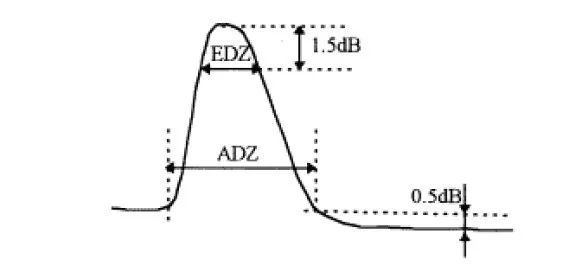
The size of deadzone is related to pulse width, reflection coefficient, loss and other factors. The shorter the pulse width is, the smaller the deadzone is, but the shorter the pulse also reduces the dynamic range. Therefore, a compromise should be made between the deadzone and the dynamic range to choose the appropriate pulse width. The deadzone at the OTDR port is also called the initial deadzone. During the test, it can be connected to more than 200 meters of pseudofibers to reduce the size.
III. Resolution
OTDR has four main resolution indexes: sampling resolution, display resolution (also called readout resolution), event resolution and distance resolution.
1. Sampling resolution is the minimum distance between two sampling points, which determines the OTDR's ability to locate events. The sampling resolution is related to the selection of pulse width and distance range.
2. The display resolution is the minimum change that the instrument can display. OTDR subdivides each sampling interval through the micro processing system, so that the cursor can move within the sampling interval. The shortest moving distance of the cursor is the horizontal display resolution and the minimum attenuation displayed vertical display resolution.
3. Event resolution refers to OTDR's resolution threshold of event points in the link under test, that is, the event threshold (detection threshold). OTDR treats the event changes less than this threshold as the uniform change point of slope in the curve. The resolution of the event is determined by the resolution threshold of the photodiode. According to the two close power levels, the minimum attenuation that can be measured is specified. It is used for OTDR's event list function.
4. Distance resolution refers to the shortest distance between two adjacent event points that can be resolved by the instrument. This index is similar to the event blind area and related to the parameters of pulse width and refractive index.
IV. Accuracy
Accuracy is the closeness of OTDR measurement value to reference value, including attenuation accuracy and distance accuracy. The attenuation accuracy is mainly determined by the linearity of photodiodes. At present, the linearity of most OTDR can reach 0.02db/db. The distance accuracy depends on the refractive index error, time base error (varying from 10-4 to 10-5) and sampling resolution. When the refractive index error is not considered, the distance accuracy can be expressed as follows:
Distance accuracy = ± 1m ± 5 × 10⁻⁵ × distance ± sampling resolution
In addition to the above performance specs, it also includes wavelength, measurement time and other indicators. In addition, most OTDR can also provide curve storage, output port, and even remote control functions.
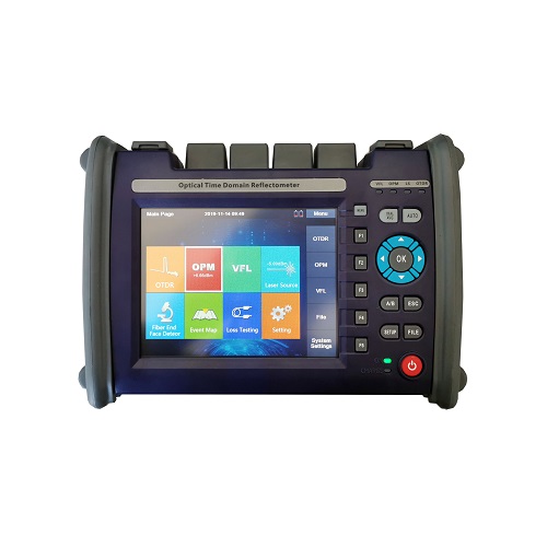
SHINHO fiber communication company is a professional supplier of OTDRs (click here for more details) with good pratical performance and real specifications. Any question or interest, also welcome to contact us! (www.xhfiber.com sales@xhfiber.com)

Welcome to register the newsletter if you have any interest in our products, we will keep you informed of our news, products information and promotions if there is any.
© Copyright: SHINHO OPTICS LIMITED All Rights Reserved.


 English
 français
 русский
 italiano
 español
 português
 العربية
 ไทย
ไทย हिन्दी
 Indonesia
 中文
中文