Categories
Latest Blog
Three Main Splice Alignment Technologies
As we all know Fiber Fusion Splicers are extremely important because the quality of the splice determines the strength of the light traveling throughout the fiber network. So we all want to get splicing machines with reliable quality.
Nowadays some manufacturers disrupted the market with price as their primary weapon, claiming to offer the same quality for less.The products are aesthetically pleasing,but lacking the most important aspect: technical know-how. This misleads lots of customers, especially for newcomers to the industry.
Today I’m gonna to talk about three main categories of fusion splicer sorted by their alignment technology, i.e. the method and mechanisms used to align the fibers to one another.This knowledge will then enable readers to choose the splicer and supplier that best meet their needs.
1) Fixed V-groove(s) – Immovable V-grooves aligned with one another that act as passive guides for bringing fibers into linear alignment with one another.
The name fixed v-groove is fairly self-explanatory in understanding how this method works. A high precision “V” shaped wedge is cut into a ceramic block, serving as a controlled surface for the fiber to rest. Once a fiber is placed in the V-groove in a splicer, a top surface – embedded in the wind protector – is closed on the fiber so contact is made at three distinct points to the fiber’s surface. This retention method restricts degrees of freedom in undesired directions. This allows the fiber to be easily moved linearly for aligning and fusing to an opposing fiber.With this category of splicer being unable to actively align the fibers, since the V-grooves are fixed, higher losses on average are imminent due to Cladding diameter variation,Core/cladding concentricity error,Dirt or coating debris in V-grooves.

The V-groove method of passively aligning two fibers was the basis for the first generations of fusion splicers, now applied to low-end single fiber splicers and mass fusion splicers(Ribbon Fibers). This alignment method was simpler to develop and cheaper to produce than the active alignment counterparts. Fixed V-groove splicers can provide sufficient results when: loss criteria are relaxed, you are splicing good quality fiber, and your V-groove’s cleanliness is maintained, which is why these splicers are still around today.
2) Active Cladding Alignment – Independent, movable v-groove(s) capable of actively aligning two fibers to each other at various locations in the X/Y plane based on cladding edge detection.
As stated previously, the active cladding alignment method utilizes the same V-groove and retention system previously described, but takes alignment a step further with motorized movement of the V-grooves. The “active” designation refers to the V-grooves that have independent electric motors which allow for travel in the X & Y directions.
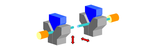
As stated in the name, the two fiber claddings are aligned to one another which is achieved via image processing. The V-groove movement is controlled by numerous software algorithms based on the fiber’s movement on-screen, making viewing the fiber and identifying the cladding edges the crux for alignment. This is not an incredibly difficult task for anyone experienced in image processing, since the splicer is only applying basic boundary conditions within the camera field of view. The splicer identifies the cladding edges, and then moves the V-groove motors until the corresponding edges are aligned to one another.
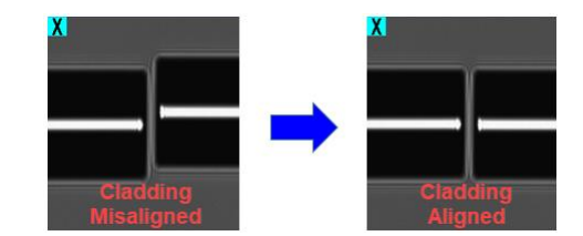
Fusion splicers which utilize movable V-grooves to provide active alignment of the fiber cladding are more craft-friendly than fixed V-groove splicers. The movable V-grooves eliminate the pre-splice cladding misalignments that may be the result of cladding diameter variations, dirt or coating debris in the V-grooves, or a combination of the two.The active V-groove splicers are most commonly used as small field-portable units suitable for FTTx and other ending network segments with loose criteria. (e.g. Shinho Fusion Splicer X-600, X-700)
The aforementioned core/cladding concentricity error pain point is unresolved with active cladding alignment and therein lies a major drawback to this category of splicer. Fibers vary in quality from manufacturer to manufacturer and vary based on age. Poorer quality and older fiber will have a larger core/cladding concentricity error, making your splices inherently prone to higher losses due to higher core offsets.Active cladding alignment splicers cannot identify different fiber types nor automatically compensate for the variances in splice parameters that different classifications of fiber require.
3) Active Core Alignment – The same v-groove system as active cladding alignment, but instead of cladding edge detection the splicer clearly identifies the fiber core’s location and aligns the two fibers based on this information.
Two fibers in a core alignment splicer are considered “aligned” when the fiber cores are positioned such that, after splicing, a single continuous fiber core results. The splicer knows alignment(both core and cladding alignment) is achieved by usage of Profile Alignment System (PAS). Accomplishing a core alignment splice requires data collection and manipulation of multiple PAS images, whereas cladding alignment is a much simpler process as was previously described. Both core and cladding alignment PAS’s make use of two collimated backlights shone through the fiber onto two CMOS cameras placed in perpendicular fields of view. From this point, the first obvious distinguishing factor of a core alignment PAS splicer from a cladding alignment splicer lies in the components comprising the optical system. Core alignment optics require higher resolution, magnification, lens quality, and the ability to change focal planes. The image below represents the hardware setup for core alignment:
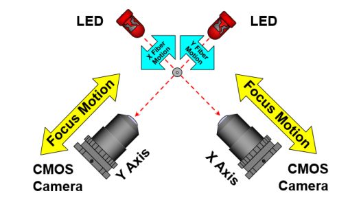
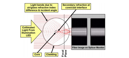
The backlight is refracted through the fiber to produce a Brightness Intensity Profile (BIP) on each camera. The cameras are observing and collecting data from the different BIPs as the cameras move through the various focal positions. Software algorithms looking for the clearest fiber core image are controlling the camera motors, and decide the final positions of the cameras. This is the same process any splicer advertised as core alignment goes through, since it is easy to observe and likewise reverse engineer. The remaining steps of the core alignment process are all programming based. There are a number of proprietary image smoothing techniques, and specific fiber knowledge used to identify the actual location of the fiber core within the bright band of a PAS image. A common misconception is that by using this hardware setup alone, core alignment can be achieved.
As was hinted at previously, the various classifications of fibers play a role in splice loss. The differing fiber types are a result of the array of applications within fiber data communication: long haul networks, undersea cables, FTTx, and high density networks, to name a few.. If you do not know what fiber you are going to be splicing, having a core alignment splicer that can detect these differences automatically is highly beneficial for painless, quality work. (e.g. Shinho Fiber Fusion Splicer X-900).
Shinho Fiber Communication Co., Ltd is with 20 years experience in developing Fusion Splicers, can supply customers with high quality splicers for different requirements. Reliable Fiber Fusion Splicer Manufacturer!

Welcome to register the newsletter if you have any interest in our products, we will keep you informed of our news, products information and promotions if there is any.
© Copyright: SHINHO OPTICS LIMITED All Rights Reserved.


 English
 français
 русский
 italiano
 español
 português
 العربية
 ไทย
ไทย हिन्दी
 Indonesia
 中文
中文