Categories
Latest Blog
The Factors Influence OTDR Testing
Fusion splicing provides the lowest loss and least reflectance, and is considered the strongest and most reliable method of joining two fibers. When properly executed, a splice can exhibit a loss of less than 0.1dB.
OTDR (Optical Time Domain Reflectometer) are required equipment for telecommunications and networking companies. It is widely used in all phases of a fiber system's life, from construction to maintenance to fault locating and restoration. The primary use of an OTDR is to locate faults such as breaks, bends or faulty splices in fiber optic cabling. They are also used to estimate the length of a fiber as well as measure its level of attenuation.
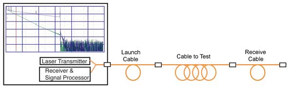
Unlike light sources and power meters which measure the loss of the fiber optic cable plant directly, the OTDR works indirectly. It operates like an optical radar, injecting multiple optical pulses into the fiber cable. These pulses travel to the end of the cable and are then reflected back to the entry or injection point. Measurements are then taken of the reflected light pulses. These measurements are then examined for deviations or changes in the reflected light wave compared to the originally injected light wave.
Proper use of an OTDR can facilitate quick repairs to fiber optic cabling and lead to markedly less network downtime. However, even a trained and experienced OTDR operator may have difficulty interpreting a fiber trace at times.
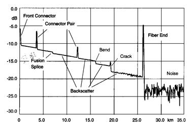
Loss due to fusion splices, connectors, breaks or macro-bends reduce the amount of returned backscatter. The OTDR records returned backscatter and reflections vs. time and may present this as a trace showing optical loss vs. distance. Intelligent algorithms interpret the trace to locate, identify and characterize detected network start, end, components and faults.
For single mode fiber, the loss is about 0.5 dB per km for 1310 nm sources, 0.4 dB per km for 1550 nm. (1.0 dB/km for premises/0.5 dB/km at either wavelength for outside plant max per EIA/TIA 568)This roughly translates into a loss of 0.1 dB per 600 (200m) feet for 1310 nm, 0.1 dB per 750 feet (250m) for 1300 nm.
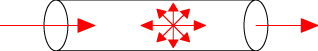
The biggest factor in optical fiber loss is scattering. In fiber, light is scattered in all directions, including some scattered back toward the source as shown here. The OTDR uses this "backscattered light" to make measurements along with reflected light from connectors or cleaved fiber ends.
Dead zone for OTDR. People who do this know that the fiber length is too short, such as less than 100 meters, and OTDR is inaccurate. This is because the OTDR cannot detect or accurately locate event points and fault points in the fiber link within a certain distance (or time) due to the influence of reflection when detecting the fiber link. The distance here is what we call the dead zone. When using OTDR for testing, since the inevitable OTDR dead zone will affect the test accuracy at the beginning and end, it will also be limited by its loss measurement accuracy and measurement range.

Welcome to register the newsletter if you have any interest in our products, we will keep you informed of our news, products information and promotions if there is any.
© Copyright: SHINHO OPTICS LIMITED All Rights Reserved.


 English
 français
 русский
 italiano
 español
 português
 العربية
 ไทย
ไทย हिन्दी
 Indonesia
 中文
中文